Fabio TaverniniSchaffhausen, Switzerland
00:00
Fabio Tavernini

D4v2 Charger

A work-in-progress board that adds USB charging to the Emisar D4v2 flashlight, so the cell can stay inside.
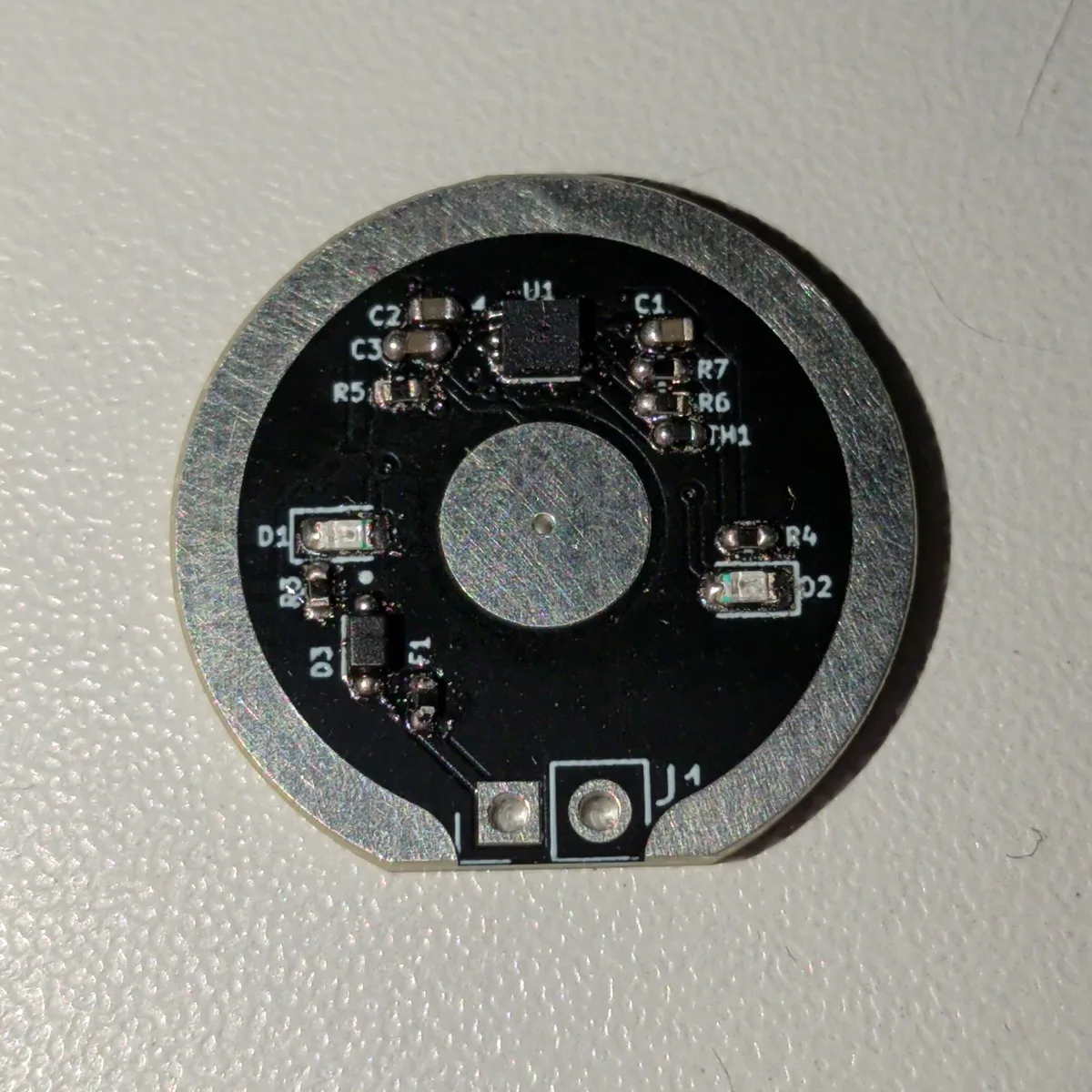
  • The assembled V1.0 prototype board, front side: a black ring PCB with a charger chip, two small LEDs, a fuse, a diode and a thermistor around a round contact pad.

    Front: the BQ25185, two LEDs, fuse, diode and thermistor.
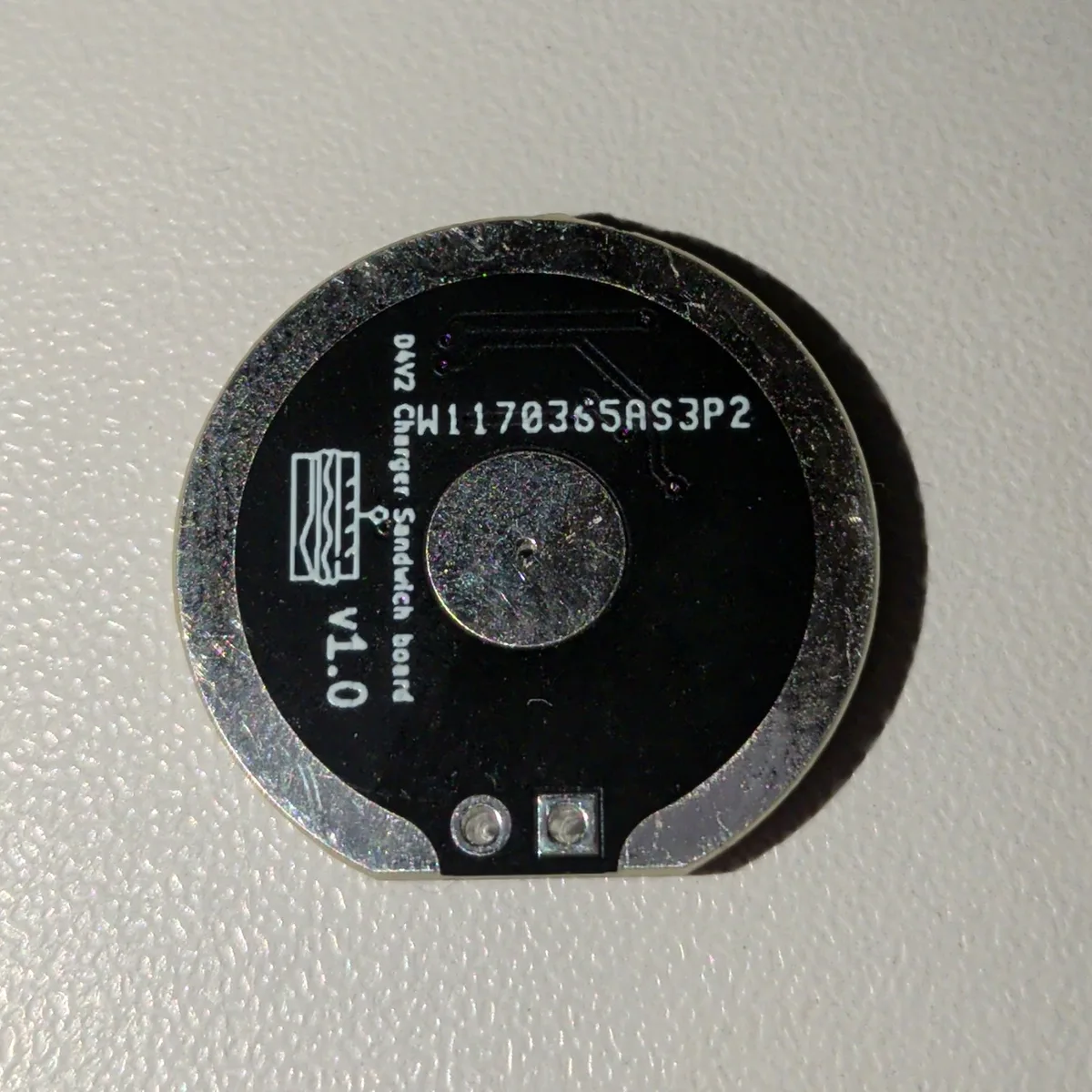
  • The V1.0 prototype board, back side, with the round spring contact pad, the text D4V2 Charger Sandwich board V1.0 and two pads at the bottom.

    Back: the spring contact pad, V1.0 silkscreen and pogo pads.

The D4v2 is a great flashlight, but charging means taking the cell out. This board turns the joint between the body tube and the head into a charging port: a ring PCB sits in the thread, a spring contact presses on the positive end of the cell, and a pair of pogo pins reaches through the body wall to bring in USB power.
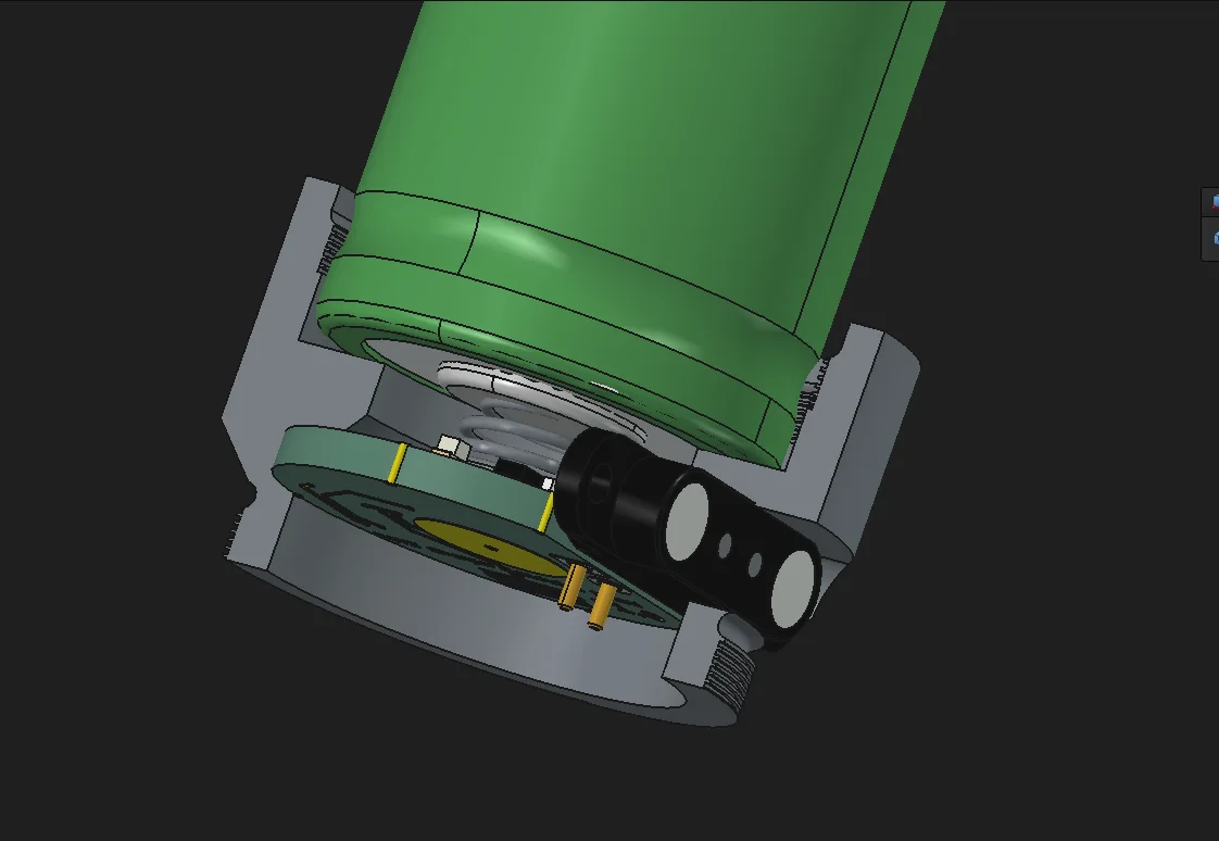
Cutaway render: a green cell above, the charger PCB sandwiched at the joint of the flashlight body and head, a spring contact touching the cell and a black pogo pin connector sticking out to the side.

How it works

  • TI BQ25185A single-cell Li-ion linear charger with an integrated power path, doing the actual charging.
  • Spring contactA 6 mm spring pad touches the cell's positive terminal, so the cell itself needs no wiring or changes.
  • Pogo pinsUSB power comes in through spring-loaded pins on a custom connector part, so the board needs no receptacle and no permanent cutout.
  • ProtectionA 1 A hold polyfuse, an NTC thermistor for temperature sensing, and two status LEDs.

From schematic to board
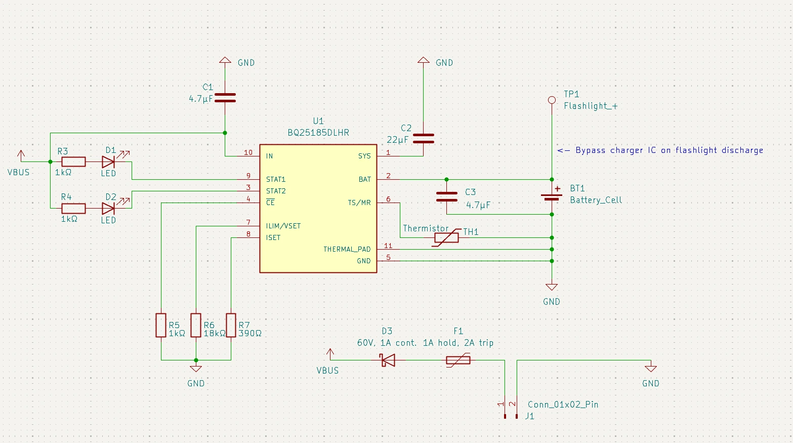
KiCad schematic: the BQ25185 charger with input and output capacitors, two status LEDs on STAT1 and STAT2, resistors setting the charge current and input limit, an NTC thermistor, the battery cell, and a diode and fuse in the USB power input.
The schematic. USB power passes a diode and a resettable fuse into the BQ25185. Resistors set the charge current and input limit, the NTC watches the cell, and two LEDs show the charge status. The flashlight contact bypasses the charger IC when the light is discharging the cell.
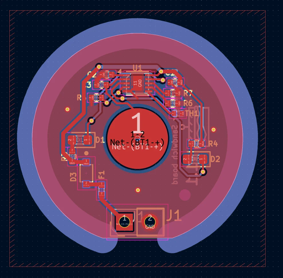
KiCad PCB layout of the ring-shaped board: the charger chip at the top, LEDs, fuse and diode around the edge, a large round pad for the cell contact in the middle and two connector pads at the bottom.
The board layout in KiCad. Everything sits on a ring around the center pad, which is the contact for the cell. The two pads at the bottom take the USB power from the pogo pins.

Made with

  • KiCad
  • FreeCAD
  • BQ25185
  • 0402 SMD
  • 0602 SMD

Status

A V1.0 prototype board has been built and assembled, and it works as a proof of concept. It is not validated in a final build yet, so expect rough edges and a V2. The schematic and layout, a FreeCAD model of the modified body and the pogo connector are all in the repo.